Ordered some exhaust bits from eBay and got them welded together by a local custom exhaust place, not the prettiest but functional and avoided having to trailer the car to the exhaust place to have it made up properly which would have cost a fortune.
So.. the first drive of the car out of the garage :-)
(Click the video once its playing to see it larger in youtube)
Who doesn't love a dump valve?
Monday, 29 August 2011
Sunday, 10 July 2011
Engine Running Properly
All back together, but it still wouldn't start. Before the clutch woes the engine was running then it sluttered out and wouldn't start again. Either meant something had burnt out electronically or no fuel/no spark for some reason. I tested all sensor resistances, the exhaust smelt petroly so I thought that was all ok, and I checked a plug was sparking while the engine was cranking. I thought maybe contaminated fuel, and was just about to start draining when we noticed a fuel pipe into the HP pump was kinked. Took the fuel line off the engine and ... no fuel! Woo Hoo! Longer bit of pipe sourced with a strip of heatshrink-coated aluminium to hold the radius and we were back in business.
Not for long though, oil leak again. Which meant (depressingly) the N/S engine mount, intercooler pipework, exhaust downpipe etc all had to come out. The turbo oil feed adaptor had bottomed out in the block - could tell because the black anodising was stripped off the first couple threads on the adaptor. Using a spare crush washer/copper washer, and loads of PTFE tape the joint was remade, we restarted the engine while it was half dangling on the crane and no leaks.
All back together, here's a video of it finally starting and running well, no leaks, nice and smooth.
Next jobs - trimming inside and getting an exhaust made.
p.s. excuse wobbly camera work on startup, watch the exhaust you'll see why! That was much louder than it was on video.
Sunday, 3 July 2011
Found another problem, but cured now!!!
So spacer machined, engine back in, clutch bled, still didn't work...
Took it all back out and with some advice from members of Locostbuilders, added a couple of washers behind the spacer to end up with a clearance between clutch fingers and thrust bearing (when fully pushed back against its spring) of about 1.2 - 2mm.
Back together, still no luck. Then read up after an extensive amount of internet searching about the gearbox input shaft possibly to tight into the spigot bearing in the crankshaft. When in 4th the clutch would slip a bit when pedal fully depressed, and in 5th moved easier, but still locked in 1-3. Suggested that something was locking eng and box together but could be overcome with enough effort. Quick and easy way to check, undo the engine to box bolts a bit, pull the two apart and stick a couple washers between each bolt hole. Back together and....
IT WORKED! Clutch depressed and all ok, biting point seemed fine. Lots of money spent replacing cylinders, fluid lines, 3 bottles of fluid and a new slave cylinder unecessarily, oh well at least we're back on track. Few hours later and hoses pipes and wires all back together. Next step - starting the engine again!
Saturday, 25 June 2011
Found the problem!
 |
| From Zero 250611 |
So new bigger master cylinder in (can see in the photo how much bigger the new one is), while the engine was out we checked carefully that we were getting full travel on the slave cylinder. I pushed slowly on the pedal while Mike held the thrust bearing pushed back as far as it would go. The full 1 inch of travel was achieved with the pedal on its highest ratio (there's three holes drilled to allow us to vary the pedal ratio). We thought we'd need to get more extension against the clutch cover to spaced out the cylinder with a few washers. Engine back in, still no luck disengaging clutch. Pushed pedal again and 'POP', fluid all over the floor... No option for it but to get engine out. How depressing.
With the engine out it seemed the slave had only slightly over-extended and pushed fluid out as the slave cylinder had gone back into the slave housing. Then after a bit of searching on Locost Builders I thought I'd take another look at the clutch plate. It had witness marks around the outside of the splined bit, it seems the fixed guide tube in the slave was permanently holding the friction disc hard against the flywheel. Some measurements taken, and without the washers we just added, there was only 0.3mm clearance between guide tube and cluth plate...
So, the spacer we had made is too thick. Looking at the clutch cover plate, the pressure ring can only come out 4mm, so we thought we'd skim 4.5mm off the spacer to give a bit of clearance. Just trying to track down a local lathe person today then hopefull we'll be back in business.
 |
| From Zero 250611 |
 |
| From Zero 250611 |
Green arrows show depth of plate from finger. Engine face to fingers = 60mm, fingers to plate = 19.3, so engine face to plate = 60-19.3= 40.7
 |
| From Zero 250611 |
This gives just 0.3mm clearance.
 |
| From Zero 250611 |
Monday, 20 June 2011
More bad times..
Disaster after disaster. We realised that due to the Omega originally running a Dual Mass flywheel which is very thick, and we are using the saab one which is thin, we'd need a spacer behind the clutch slave to make up the distance. Using our previous measurements where we thought all would be fine, we realised that when clutch and gearbox are mated the thrust bearing is pushed back against the spring around the clutch slave (this should make sense if you're looking at it). The thrust bearing is always pre-loaded against the clutch fingers.
Measuring it extended and fully depressed came to 25mm ish, so we had a spacer bought from SBDEV, part ref CLT-HCS-30, lathed down to 24mm.
Fitting it all back together, we bled it through to get what felt like a firm pedal. However depressing the pedal the full travel of the 3/4" bore Land Rover Clutch Master didn'r release the wheels from the engine. Some head scratching and it seems we just aren't shifting enough fluid to fully extend the the slave. So we found a single port 1" dia brake reservoir for a Series 3 Land Rover on ebay and ordered that plus a reservoir. Waiting for delivery to see if we can finally get a break with this build!
Monday, 6 June 2011
Engine Running

Sunday, 5 June 2011
Disaster!!!
So with the engine in and all wired up we started to fill it with fluids. Water went in, leaked from various places, tightened things up, water stopped leaking. Realised that you have to have almost perfect size matches i.e. you can't get away with putting a 40mm hose on a 38mm pipe - it'll leak! No matter how tight you tighten it.
Oil filled up, leaked everywhere - forgot to tighten the oil unions in a couple of places which seems pretty basic but it's easily done!! Also the oil filter leaked slightly as there's so little chassis clearance you can't get a good hold.
Put clutch fluid in, spend ages bleeding it but no pressure in the pedal. Eventually found the fluid dripping out of the gearbox bellhousing... NOOOooooo...
So it appears that the seals are gone on the slave cylinder, so engine out again. This is very depressing - the car looks a mess again and it almost looks the same as it did a year ago. These things happen I guess - the lesson here is don't trust anything, check it before fitting; a few minutes saved can prevent days of misery later.
One concern is the actual use of the Saab flywheel and Omega clutch. When we put the engine and g'box together we measured clutch face to engine block, and slave cylinder to bellhousing mounting face. These appeared to match so all was thought ok. But its possible the slave cylinder had been locked in the out position from being over-extended. Reading up more, it seems that as we're using a normal saab flywheel, not the thicker dual mass omega flywheel, we have some extra space to take up. This means we might need a spacer under the slave cylinder.
Oil filled up, leaked everywhere - forgot to tighten the oil unions in a couple of places which seems pretty basic but it's easily done!! Also the oil filter leaked slightly as there's so little chassis clearance you can't get a good hold.
Put clutch fluid in, spend ages bleeding it but no pressure in the pedal. Eventually found the fluid dripping out of the gearbox bellhousing... NOOOooooo...
So it appears that the seals are gone on the slave cylinder, so engine out again. This is very depressing - the car looks a mess again and it almost looks the same as it did a year ago. These things happen I guess - the lesson here is don't trust anything, check it before fitting; a few minutes saved can prevent days of misery later.
 |
| From Zero 050611 |
 |
| From Zero 050611 |
One concern is the actual use of the Saab flywheel and Omega clutch. When we put the engine and g'box together we measured clutch face to engine block, and slave cylinder to bellhousing mounting face. These appeared to match so all was thought ok. But its possible the slave cylinder had been locked in the out position from being over-extended. Reading up more, it seems that as we're using a normal saab flywheel, not the thicker dual mass omega flywheel, we have some extra space to take up. This means we might need a spacer under the slave cylinder.
Dashboard
The dash comes in 2 layers from GBS, an inner layer that gets its tabs bent to fasten onto the scuttle and an outer slghlty larger layer that you cover and make look nice with Vinyl or similar. GBS do a glassfibre one now with the IVA required rounded lower edge radius of 19mm, but the IVA manual also appears to suggest as long as its padded the radius can be less than 19. So Mike is planning of riveeting the inner in place, the rivets will then be covered up with rubber edging strip. The outer then gets padded, using a camping roll mat! £5 from Argos. This is covered in vinyl and cutouts made for the gauges. Will try to get more photos of it all held together but here's a quick 'lights on' shot.
The aluminium plate is 5mm i think, with a Bright6 module mounted behind (symbol decal not added yet), a cig lighter socket for phones/satnav and a switch for the fog. This has a 'tell-tale' LED in it so you know when the fog is on or not.
 |
| From Zero 050611 |
The aluminium plate is 5mm i think, with a Bright6 module mounted behind (symbol decal not added yet), a cig lighter socket for phones/satnav and a switch for the fog. This has a 'tell-tale' LED in it so you know when the fog is on or not.
Saturday, 14 May 2011
Back to the floor!
Time to drop it off the tressles, not far to go now! Also, not much space left in the engine bay..
 |
| From Zero 130511 |
Nose Cone
Lower mounts using bit of ally plate, rivnuts and nuts and bolts. Make sure you put the bonnet on to check position and height of nose cone before you mount it!
Small cutout made for water hose.
The top mounts are ally angle spaced off the chassis with a couple of pieces of 3mm ally strip, secured to the chassis via rivnuts, with M5 countersunk screws securing the nosecone onto the angle where the bonnet will hide the screw heads.
Small cutout made for water hose.
 |
| From Zero 020511 |
 |
| From Zero 020511 |
The top mounts are ally angle spaced off the chassis with a couple of pieces of 3mm ally strip, secured to the chassis via rivnuts, with M5 countersunk screws securing the nosecone onto the angle where the bonnet will hide the screw heads.
 |
| From Zero 050611 |
Oil cooler pipes
M20x1.5 to 1/2" BSP fittings from
1/2" BSP to 1/2" hose tail, from ebay
Mocal push-on oil hose, 1/2" bore from ebay
1/2" hose tail again
1/2" tap connector from Screwfix
1/2" copper plumbing pipes (!) to more tap connectors
5/8" (cooler) to 1/2" adaptors from ebay I think.
Sprayed matt black to look less home made...
1/2" BSP to 1/2" hose tail, from ebay
Mocal push-on oil hose, 1/2" bore from ebay
1/2" hose tail again
1/2" tap connector from Screwfix
1/2" copper plumbing pipes (!) to more tap connectors
5/8" (cooler) to 1/2" adaptors from ebay I think.
Sprayed matt black to look less home made...
 |
| From Zero 020511 |
Wiring pt1
So onto the wiring - a mammoth task given the amount of Saab wiring I had to try and sort out - bearing in mind the Saab had electric everything and its many computers monitored all sorts of things. There was lots of stuff to bin and it took many weeks deciphering wiring diags.
Starting with the Zero Loom, a hole was cut for the fuse box. This had 2 spare fuse holes so I used these for the fan and the fog light. Zero loom does not have in my opinion good enough wiring for the fog and horn, and nothing at all for the fan so I re-used relays and wiring from the Saab to run them.
For anyone who doesn't have this, its the connections required for the column and ignition wiring.
pin ford gbs purpose
headlights 15 brown white (thin) ignition
headlights 56 brown black brown black link
headlights 56a brown yellow white orange main beam
headlights 56b brown white orange black dip beam
indicators 30 red brown (thin) constant feed
indicators 49 black red green flasher relay feed
indicators 54 black white (thin) ignition
indicators 49a black white green yellow feed to flasher unit
indicators L black white green red left indicators
indicators R black green black green right indicators
lights 30 red brown (thin) constant feed
lights 31 brown white (thin)
lights 55 empty
lights 56 brown black brown black link add wire to fog light switch
lights 58 grey red side lights
wipers 53 green yellow blue slow speed
wipers 54 black violet white (thin) ignition
wipers 53-2 black green
wipers 53a black violet
wipers 53B red grey red fast speed
wipers 53c black orange washers
wipers B1 brown white
wipers B2 brown yellow
wipers W black yellow
ignition switch black yellow white (thick) ignition
ignition switch red brown (thick) main feed
ignition switch black blue white red starter
ignition switch yellow accessory
red white horn
black earth
grey fuel sender
yellow black brake warning
Starting with the Zero Loom, a hole was cut for the fuse box. This had 2 spare fuse holes so I used these for the fan and the fog light. Zero loom does not have in my opinion good enough wiring for the fog and horn, and nothing at all for the fan so I re-used relays and wiring from the Saab to run them.
 |
| From Zero 020511 |
For anyone who doesn't have this, its the connections required for the column and ignition wiring.
pin ford gbs purpose
headlights 15 brown white (thin) ignition
headlights 56 brown black brown black link
headlights 56a brown yellow white orange main beam
headlights 56b brown white orange black dip beam
indicators 30 red brown (thin) constant feed
indicators 49 black red green flasher relay feed
indicators 54 black white (thin) ignition
indicators 49a black white green yellow feed to flasher unit
indicators L black white green red left indicators
indicators R black green black green right indicators
lights 30 red brown (thin) constant feed
lights 31 brown white (thin)
lights 55 empty
lights 56 brown black brown black link add wire to fog light switch
lights 58 grey red side lights
wipers 53 green yellow blue slow speed
wipers 54 black violet white (thin) ignition
wipers 53-2 black green
wipers 53a black violet
wipers 53B red grey red fast speed
wipers 53c black orange washers
wipers B1 brown white
wipers B2 brown yellow
wipers W black yellow
ignition switch black yellow white (thick) ignition
ignition switch red brown (thick) main feed
ignition switch black blue white red starter
ignition switch yellow accessory
red white horn
black earth
grey fuel sender
yellow black brake warning
Tunnel Tops
A little out of sequence in the build, but the tunnel panels were trimmed in vinyl with spray contact adhesive from Halfords and bolted with Rivnuts and dome-head socket bolts
 |
| From Zero 020511 |
Fuel Filter
Found on ebay for 99p! Just an injection filter for an Omega or Astra or something. Aluminium sheet cut to strips to make brackets, Rivnutted onto the pedal box.
 |
| From Zero 020511 |
Accelerator Pedal
The pedal didn't provide enough travel to fully open the throttle butterfly so I welded a piece of 3mm steel onto the pedal and also made a clevis out of 3mm plate and some nifty welding to allow for the rotation of the pedal.
Slightly tricky to see but there's the single strip of 3mm metal, roughly 12mm x 40mm with the first 10mm of it welded to one side of the top of the pedal, a 5mm hole in the top of that strip, a clevis which is really just a U-shape made from 3mm strip, all linked together with an M5 cap head and washers to space it out.
 |
| From Zero 050611 |
Slightly tricky to see but there's the single strip of 3mm metal, roughly 12mm x 40mm with the first 10mm of it welded to one side of the top of the pedal, a 5mm hole in the top of that strip, a clevis which is really just a U-shape made from 3mm strip, all linked together with an M5 cap head and washers to space it out.
Throttle
After another lull in posting, we have some more progress to report!
Throttle cable action - used a bike brake cable, the barrel shaped nipple on the cable fitted into the original Saab throttle linkage. At the other end a cable nipple from ebay was purchased. The threaded adjuster is off an old bike brake lever I had in my stock of bits and pieces I've hoarded in the garage. You never know when things come in handy!
The aluminium plate bolted onto existing holes in the throttle body, to provide a cable stop. Shaped with a hacksaw and files, from strips of aluminum and aluminium angle, then low-temp welded/brazed again.
Throttle cable action - used a bike brake cable, the barrel shaped nipple on the cable fitted into the original Saab throttle linkage. At the other end a cable nipple from ebay was purchased. The threaded adjuster is off an old bike brake lever I had in my stock of bits and pieces I've hoarded in the garage. You never know when things come in handy!
 |
| From Zero 020511 |
The aluminium plate bolted onto existing holes in the throttle body, to provide a cable stop. Shaped with a hacksaw and files, from strips of aluminum and aluminium angle, then low-temp welded/brazed again.
 |
| From Zero 020511 |
Thursday, 27 January 2011
Seats
Not much to say, seats & harnesses fitted! Mounted straight onto the steel floorplan, driver's seat on sliding brackets from GBS.
 |
| From Zero Dec10 |
Inlet Manifold
We used a Saab 9000 manifold as it has the inlet on the end rather than the 900's original one that went over the top of the engine and was way too high to even consider using. The issue was that the inlet faced into the bulkhead so we cut off the ends and rewelded the opposite way round. Was tricky to get it all lined up but made an MDF jig to help matters. We used a low temp aluminium brazing kit from ebay (£15) and a plumber's type propane torch - it worked for the manifold cutoff onto the flange but was not powerful enough to heat the mass of metal of the manifold to get the solder to flow properly so we enlisted the help of someone with Oxy-Acetylene, the bodged up the leftover holes with JB Weld. Fingers crossed it works.
Ends cut off.
Rough position it will end up in. Used 70mm OD aluminium pipe to extend mounting position.
 |
| From Zero Dec10 |
Ends cut off.
 |
| From Zero Dec10 |
Rough position it will end up in. Used 70mm OD aluminium pipe to extend mounting position.
Intercooler
We bought an Intercooler for a Toyota Mr2 Turbo off ebay and used 1" angle rivnutted to the chassis. There wasn't enough room to put it in front of the radiator with the fan fitted, the rad sits very far forward in the Zero. We will add a lot of ducting to channel cold air to the cooler.
 |
| From Zero Dec10 |
 |
| From Zero Dec10 |
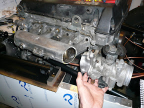
More engine installation work
So, nearside rail removed, turbo now fits, but we turned it round 180 degrees on the manifold flange.
Will mean some replacement of oil and water hoses using banjo fittings (M12 I think) and high temp oil/water hose. Also the bit turbo inlet hits the block so that will need trimming back.
 |
| From Zero Dec10 |
Will mean some replacement of oil and water hoses using banjo fittings (M12 I think) and high temp oil/water hose. Also the bit turbo inlet hits the block so that will need trimming back.
Engine mount, sump
Top view showing n/s engine mount and chassis rails
Close up of engine mount spacers, turned from aluminium
Shows how much the sump sits below the chassis.
As can be seen, that chassis rail will have to go.. a quick look on the net shows many 7 kits only have 1 rail so we're not too worried about chassis strength.
 |
| From Zero Sep10 |
Close up of engine mount spacers, turned from aluminium
 |
| From Zero Sep10 |
 |
| From Zero Sep10 |
Shows how much the sump sits below the chassis.
 |
| From Zero Sep10 |
As can be seen, that chassis rail will have to go.. a quick look on the net shows many 7 kits only have 1 rail so we're not too worried about chassis strength.
 |
| From Zero Sep10 |
Long time, no blog
Due to Mike's laziness the blog hasn't been updtaed for ages so here comes some brief updates to where we are now.
In summary, the damn Saab engine doesn't really fit!
In summary, the damn Saab engine doesn't really fit!
Subscribe to:
Comments (Atom)